
Sep '04 - Aug '08
4pm on Sunday with a final jury rapidly approaching at 9am on Wednesday. Plans done? Nope. Sections? Nope. Model, renderings, animations? No to all. Yet, what we're learning today, if nothing else, is that even when you're not being productive there's still room for procrastination.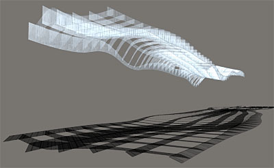
Portion of final cloud form showing the varying, disparate thickness of the ribs
Initially, to find the form of the cloud we started with a flat NURBS plane and then began distorting it to create curatorial zones on the floor of the booth. The result was a highly curved magic carpet-like plane floating in space. This plane provided the ruling lines for the structure. The schematic design rendering depicted a cloud of consistent thickness, but we wanted to push the idea a bit further by developing it into a thin, more cloud-like volume. Moving from a plane to the actual thin volume of the cloud required an act of inflation that would address assembly, structural integrity, and preferably result in something with varying thickness.
Always fighting against cost and time, in this project we were obliged by schedule and budget to find ways to reduce both. Our answer came as a synthetic move that addressed all of the problems mentioned above by considering an unlikely suspect: tool paths. In an attempt to nest the individual ribs as best as possible to save on material usage, we discovered that letting the logic of the cutfile dictate the specific inflation of the cloud would not only reduce our cutting time and material usage, but also provide an unexpected thin volume caught between the upper and lower surfaces of the cloud.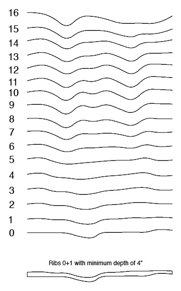
The magic carpet plane became the bottom surface of the cloud which meant that the bottom profile of each of the ribs would need to be taken exactly from a spline on the surface of the carpet. The top, however, was undefined in the carpet and so we decided to use the profile of the next rib in the cloud to define the top profile. By spacing the profile splines such that no two vertically-aligned points are less than 4" apart we developed the thickness of the cloud as a derivative of its curvature. This allowed us to nest ribs so that two functional edges are cut with one pass: piece 0+1 sits right next to 1+2, 2+3, etc...
With this form finding technique established it was a matter of finding the right minimum offset to balance material use and desired effect and then going through the laborious motions of adding the slots that would facilitate assembly. The renderings below depict a 4'x16' section of the cloud and demonstrate the varying and disparate thickness of each rib.

")


8 Comments
looks good. what is it going to be built from?
Check the initial post about this project for more background. It's 6mm cellular polycarbonate... about 800 lbs of it. There are also a few acrylic pieces that act as lynch pins.
i love the economy. so many curvilinear projects forget about material waste.
i think it's going to look better built than in the renderings, and that is no mean feat!
good luck, and good procrastination.
javier- material waste was specifically one of our concerns and that's exactly why we devised the technique that we did for generating the form. In the absence of the cutfile itself (I'll post the image later when I have it handy) it may be hard to understand, but they were designed to have very little waste. In the end we ended up with more waste than expected because the fabricator couldn't cut the files as they were drawn, but just because something is curvy does not mean it has to generate extreme waste. Typically curvy projects end up with sheets littered with pieces that are floating because they share no edges (think NOX), however our pieces were designed to share edges meaning no waste between them and much shorter tool paths. This, I believe, is fairly important because it's acting critically with the tools (and tool paths), not just using them as output devices for curvaceous digital dreams.
Wow. I just read you initial post, and I am impressed. Last year (or two) we did a workshop with the aim of building a model of the sky over Malmoe. Had ours been half as good as yours I would have been really proud. Of course MDF and foam was a lot less advantageous as materials... And I was kinda clueless back then.
Still, being a Swede it sparks a bit of envy that Harvard students steal our nice projects.
Cheers!
Great job. I can't wait to see the final built structure.
welcome to Hahvahd
Block this user
Are you sure you want to block this user and hide all related comments throughout the site?
Archinect
This is your first comment on Archinect. Your comment will be visible once approved.