The components that make up this airport include a 3,000 meter long asphalt runway that receives almost 150 planes a day. This runway is open 24/7, something that would've been a concern if located in the mainland urban fabric. It is lit up by 5,000 lights that cost 37,000 dollars to light up a month. The location becomes an advantage when fuel is concerned. Tanker ships can pull up to 4 docks to deliver this fuel, and the storage area can store enough to fuel planes for a whole week. The island acts like its own community, it has its own incinerator plant for all the trash that comes off the planes.
The entrance to this 4 floor structure is referred to as the canyon. It is 30 meters high and 300 meters long providing a view from one end all the way to the other. There are 99 escalators and 92 elevators to help circulation flow smoothly. The 5,000 windows are held in place by flexible joints that anticipate the high speed winds.
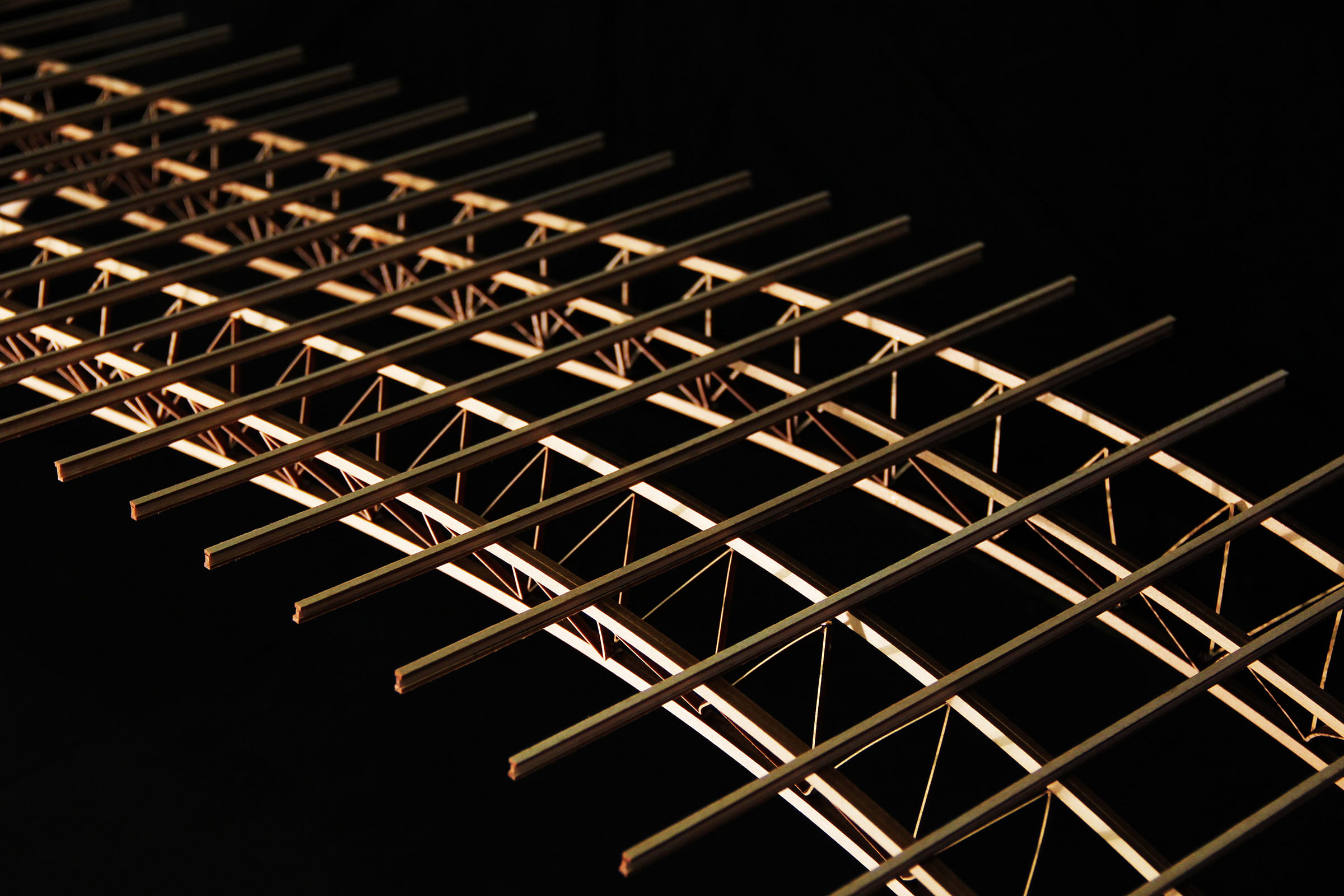
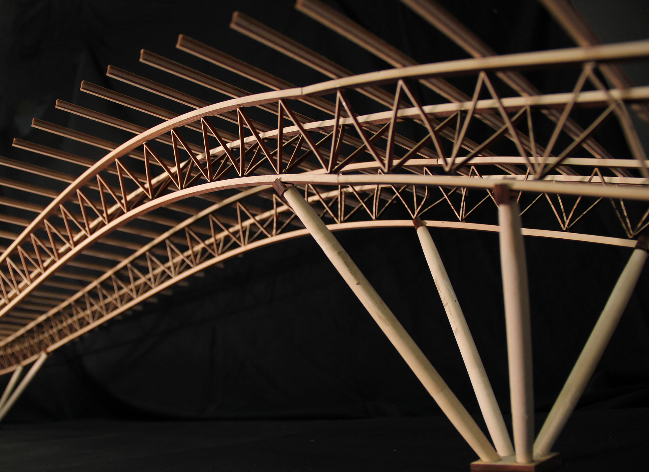
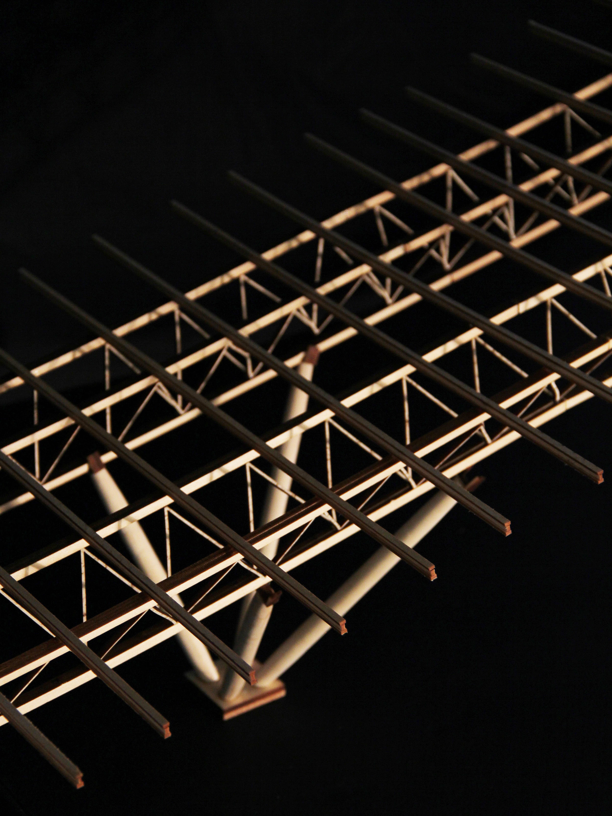
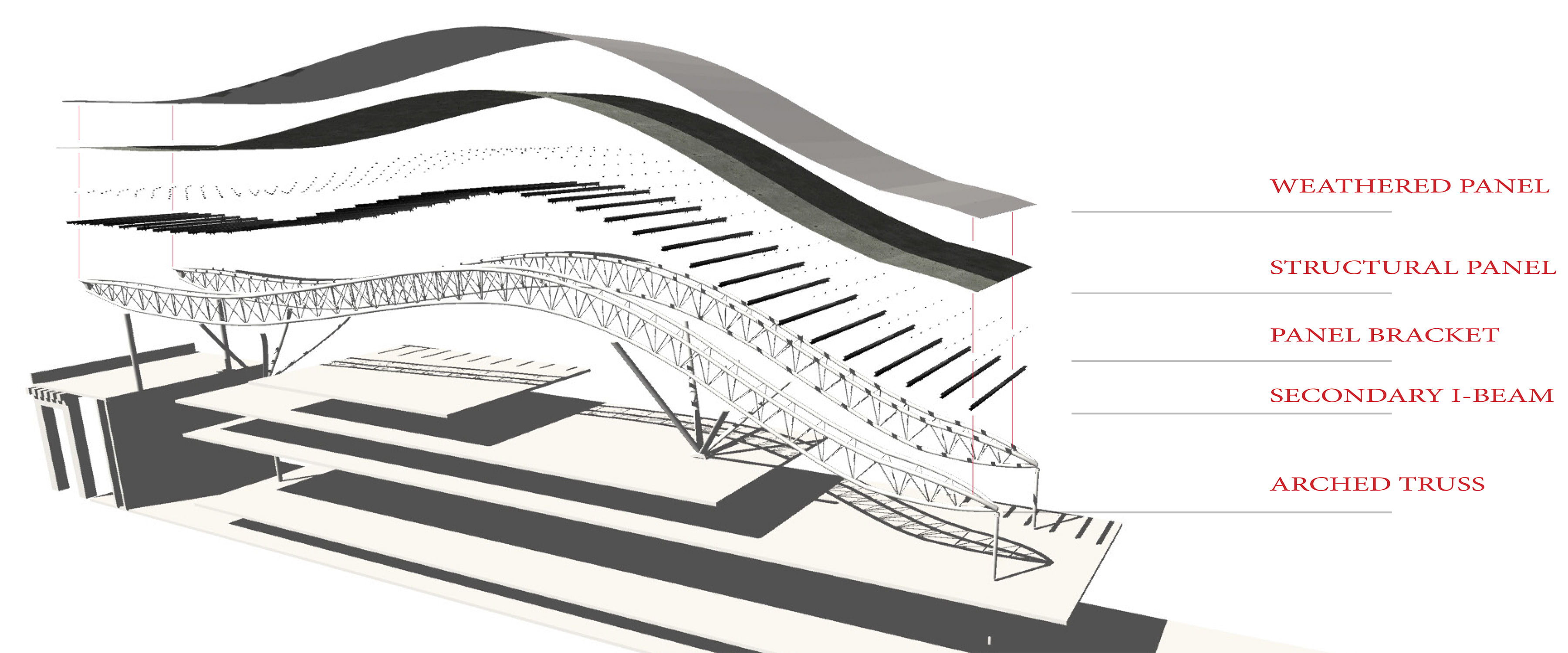
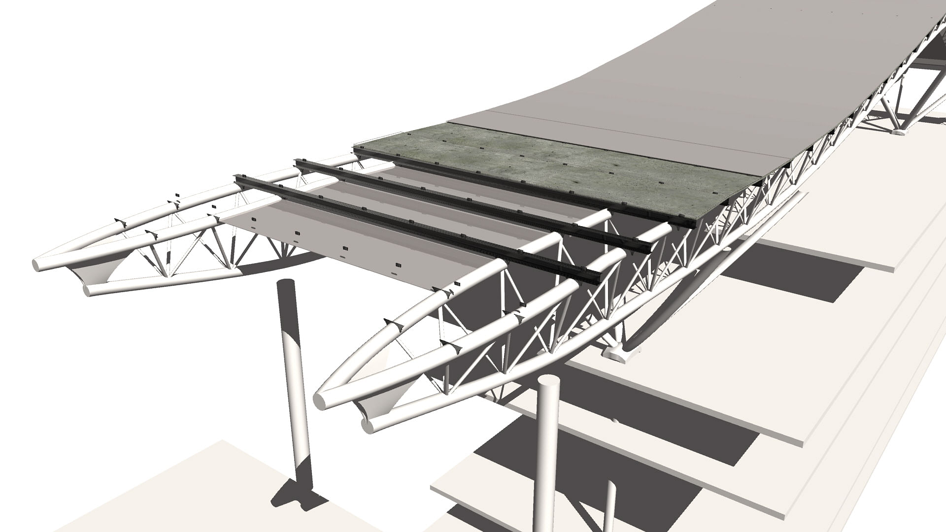
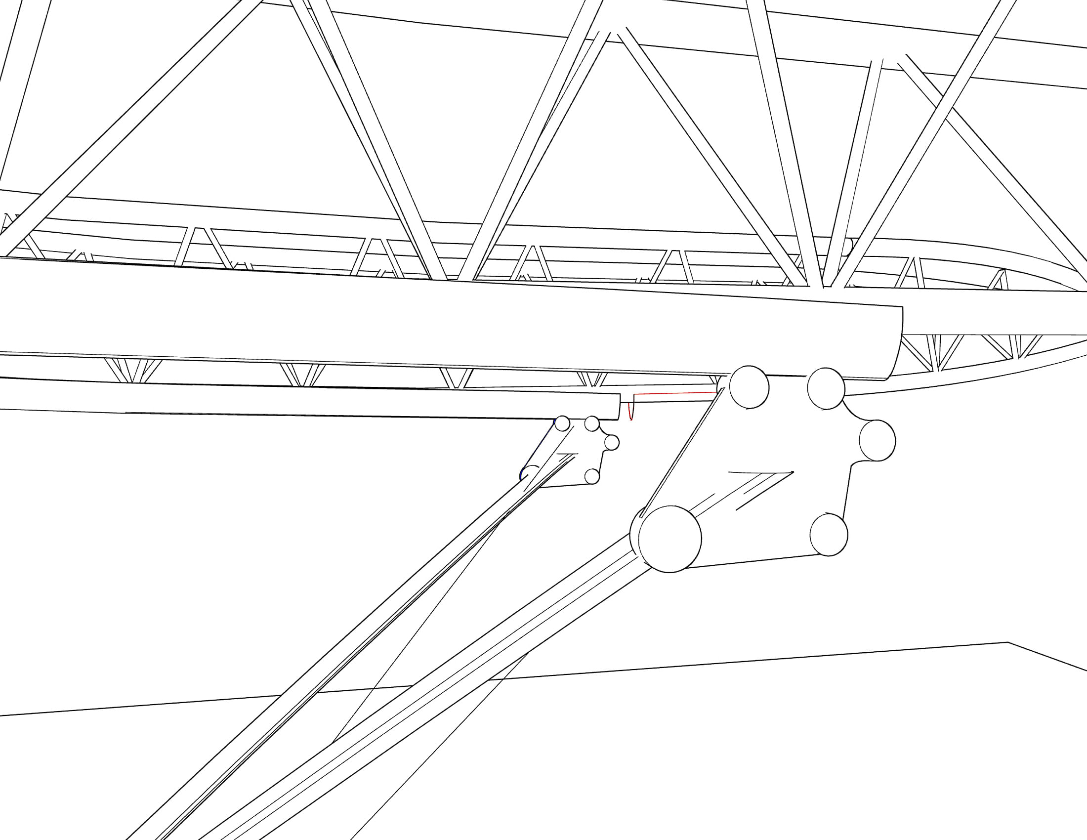
The foundation is made up of 900 pillars that sit above 360,000 tons of iron ore that replace the excavated soil. In the main terminal, the primary structural system can be identified as a series of warren based, triangular three-dimensional trusses. These trusses are arched in a way that mimics the shape of the curvilinear roof located above. There are a total of 18 trusses placed at a distance of 14.4 meters apart. Each of these spans 82.8 meters. To provide support for these long span trusses, a secondary structure was designed to provide stability. Made up of I-sections that are cross braced, this helps absorb any lateral forces and restricts any buckling from occurring.
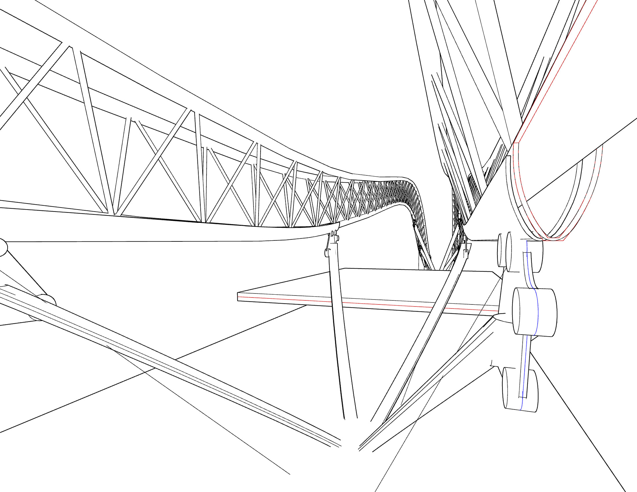
Facing the ocean, we have the ‘Wing’ of the megastructure. This curved section spans across the entire 1.7km and receives the highest amount of stress, mainly coming from the winds generated by storms and typhoons. The additional pressure calls for a separate structural system. This system can be described as a series of single cylindrical steel members that act as columns to resist compression, along with tension cables that provide support. In this case, shear was an issue, and the secondary system was designed to resist this.
Another roof form generating idea was the desire to condition the passenger terminal without a clutter of ductwork hanging from the exposed trusses. This was done by blowing a jet of air from the land side and let it be carried against a ceiling that would be shaped to follow the natural curve of the decelerating air. Huge scoop like ceilings entrain the blown jets of air across the space.
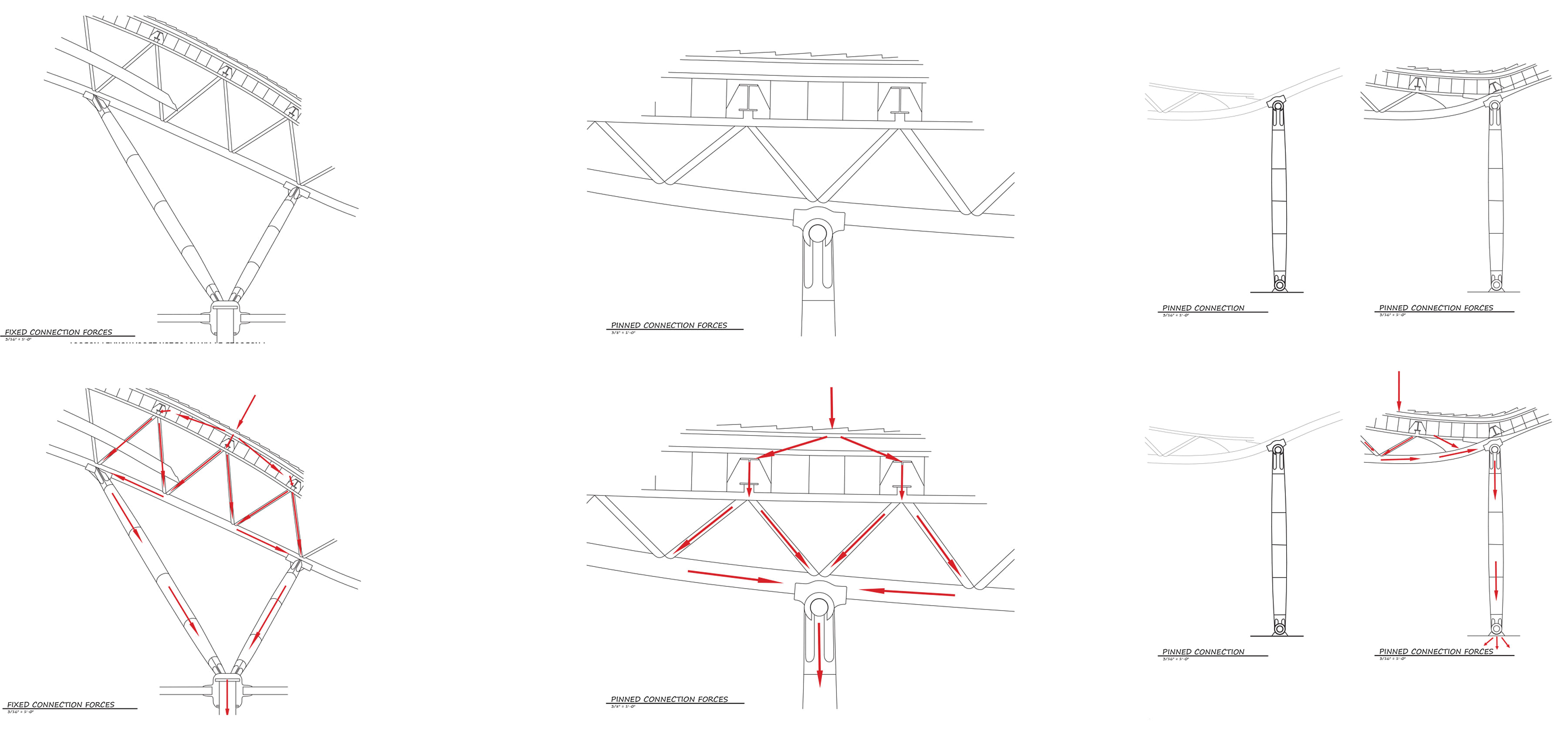
The ground connection and the row of columns provide the vertical supports. To connect the structure and the envelope, double bow trusses are used to minimize the complexity of the connections.
82,000 stainless steel tiles each measuring 1.8 x 0.6 meters weighing 10 kilograms cover the double roof. These were selected to provide ease of installation and reflectivity of the material protects the inner roof. The drainage system keeps it in good condition. In order to combat uplift, these tiles flex and lift in the center.
The cladding is made of glass panes measuring 3.6 x 0.6 meters that are all treated as individual units. These are arranged in a way that follow the geometry of the roof. Due to thermal issues, these have expansion joints to absorb the movement. There are also rubber elements that help with weatherproofing.
Status: School Project
Location: Osaka, JP
My Role: Case Study Coordinator
Additional Credits: Sultan Samhan & Brady Daniels