Second...off... I have three really old but really beautiful columns supporting my porch roof (the roof has a sun porch above it) I want to restore these columns and even beef up their support capabilities if I can.
Does anyone know where I can find data on the amount of load that wood columns can support?
Also does anyone know of any resources I can look into to restore wooden columns?
This topic might be more appropriate for a contractor forum, but those buggers are useless.
Without seeing what you are dealing with it's a little hard to answer.
For the structural end I'd say figue mak cross section, do the math and that's what you get. The unfortunate part is that you may want to deduct depending on condition. If they are builtup column, on the other hand, you may be able to beef them up but typicall this is not the case.
As for restoring, I would talk to you local timber framers and/or furniture restoation guys (depending on what you have). They should be able to direct you down the right road.
what are the columns resting on? do they go to the ground into conc ftngs (i assume), can you estimate what the current load is based on common methods of material quantity and weights and measures?
this can give you an idea of their current load and how much room you have to add to them, then you can build up members
do you know a engineer? might not want to (might not legally be able to execute) go down this path alone if youre not comfortable and actually going to do something here
Wow, I wasn't expecting responses till at least lunch time, thanks alot guys.
The columns are 5.5' long, 8" doric columns (I think).
They rest on a concrete pad on a brick column, basically the bottom of the column is about 6 ft from the ground
They support a 19'x8 1/2' sun porch, I did a quick load estimate a while ago but forgot the number. The sun porch is meant to be accessed by people though so I added about 400lbs for myself, the wife and the pets.
The sun porch itself is made of a floating deck (15x7 in size) of 1x6es on 2x4s on a EPDM membrane on 3/8" plywood of 1/2" original TnG boards on 2x4 (actual 2x4 not 1.5x3.5) joists (about 20 or so) sitting on 2x10s which are supported by the three columns up front and on two brick outcrops from the home itself out back. I figure the total load is about 400lbs plus 300 lbs for the material with no factor of safety. Assuming they followed the 20lbs/sq ft rule for outdoor structures with live loads, the sun porch should hold 3200 lbs of load or so.
I'm not sure about the material, I haven't removed enough of the paint, they're probably pine or cedar and roughly 40 or more years old, probably hollow core too, no air holes at the bottom (unless they are covered in layers of paint and I haven't noticed yet)
They may have some rot issues and definately have cracking issues b/c the prior owner never bothered to properly waterproof the deck of the sun porch above and thus they have experienced some water damage, I'm not really sure how much damage they've experienced but so far my prodding, poking and paint removal has not turned up any signs off disintegrating wood or insect damage. Although there are plenty of vertical cracks on one of the columns (the centre one) and peeling paint on both the base and top of the columns.
I epoxied and wood fillered some of the damage last summer, but I did a quick job on it so as to determine how much the waterproofing problem on the porch deck above is affecting the columns.
I'll try to get the wife to take some shots and maybe I can toss them on here by lunch time.
to see if they are hollow, you might be able to probe some small holes(top,mid,bot), -1/16" and insert a ductile wire with a small hooked end and twist to see if you can rotate it, or something or other like this
if it is hollow it will give you at least a thickness, mark the wire with some crayon or something and you can measure from the bend to the mark
Columns such as you describe are Hollow made up of small pieces of wood. If you look up the company "Turncraft", they make Wood columns and have the load carrying capacity for columns based upon
diameter of column. It will give you a very good idea as to the load
carrying ability of your column. I will post a picture later of what your
column might look like cut in half. I happen to have one in my garage.
I had the impression that the columns were hollow and made from small turned pieces of wood.
Turncraft was a great resource, it sorta confirmed my own ideas about how much load the columns can bear, although I've decreased the load number they've provided significantly for my own application.
What this means for me is a messy weekend stripping paint off the columns and trying to fix any damage, hmmm I can almost smell the epoxy now. But at least I most likely do not need to replace.
BTW does anyone know where to get Dutchman clamps or permanent band clamps?
I'll post the pics soon, the wife is watching the bloody Tyra show and apparently that's more important ;-)
If your contemplating restoration/renovation the building department will probably hold you to the current code and that probably means uplift resolution on your column assembly. I do these details all the time for work and typically use 2 approaches:
1. 4x4 wood post core – With this approach you can have simple Simpson connectors at the base and top of the wood 4x4 post to counter uplift forces. If you are on a masonry/concrete plinth you will need to install an epoxy anchored elevated post base (elevated so the post does not absorb moisture from the concrete and prematurely rot) at the bottom of the assembly. At the top of the assembly, depending on the existing framing either a Simpson post cap or a Simpson strap will do. This assembly requires that you order your new columns (I’m assuming you are replacing them) split.
2. Cable core – If you are keeping your existing columns they will be hollow at the core. For this detail I have used aircraft cable epoxy anchored at the concrete/masonryplinth and with an “eye” lagged into the existing framing at the top. Tightening the assembly is the tricky part and a come-along will help there.
A few notes on columns:
New wood columns are not like the ones from 50 years ago. The new fast-growth lumber tends to rot quickly (just a year) if the columns are not installed correctly. Order them in redwood with lock-joint construction and asphaltum treaded cores.
If you are placing the columns on a concrete/masonry plinth order new columns with aluminum plinths to separate the wood from the concrete.
Ventilation and flashing are the key to keeping wood columns around. Make sure you review the manufacturer’s venting and flashing details and follow them exactly. Have a metal shop make you up copper flashing caps and drill vent holes in the tops under the beam to allow ventilation (the aluminum plinth will have ventilation openings).
I prefer columns from Harman Sanders. Their columns have the nicest details and best looking entasis. Hartman Sanders are expensive. Somerset is my second choice.
Both Harman Sanders and Somerset make cast columns (Duracast) that feel like real wood columns (not the thin fiberglass junk) that are a preferred solution for outdoor columns but at lengths less than 8’ they are hard to come by.
Read up on column proportions (entasis is 1/3 total height) and don’t cut the shaft to a point that the vertical section of the entasis gets too short – the columns will look bad.
You can also use fiberglass columns. i know it seems unpure but the strength is tremendous compared to wood and once painted they look like glossed painted wood anyways, no rot ever.
threshold,
I can't really buy new columns, my cash supply is pretty thin, that's one of the reason why I want to restore my old columns.
I've looked into the building codes and as long as I'm not removing anything I'm ok. I may need to sister an extra joist or two to the underside but then again I may not.
Also how do I go about making that "Cable Core" support thing are there any reference documents you know of?
crowbert,
I think your calcs might be more accurate than mine, I forgot to add snow load to my load calcs.
Just a question though, there are five points supporting this porch, the three columns and 2 wall outcroppings supporting this porch (the outcrops and 2 of the columns are at the corners.
Does this mean I can divide the total load, 8075 lbs by 5?
Divide span in half from existing building to column line.
Divide column half in quarters.
The columns on the end support a quarter each (or 1/8th the total load) and the one column in the center supports two quarters (or 1/4 the total load).
The ledger attached to the building supports a uniform load (as opposed to point loads, which are the columns) which is 1/2 the span (either 4.25' or 9.5' in your case) times the #/ft. (uniform loads are measured in #/linear foot, so its 1/2 span x 1' wide)
If they are not going to hold you to uplift I wouldn’t worry too much about it. You can get everything at Home Depot and the only specialty tool is a cable crimper (I have the inexpensive Home Depot version and it works just fine – the nice stage set ones are big bucks). Pick up some stainless aircraft cable, a stainless steel lag-end eyebolt for attaching to the framing above, a stainless steel threaded eyebolt at least 4 inches long, a Simpson epoxy anchor kit (rent a hammer drill if you don’t have one) and some crimps for the aircraft cable.
As for the setup, just imagine the cable running vertically through the center of the column with an eyebolt embedded in the concrete base at the bottom and the other lagged to a joist of solid blocking above the column. If you can lag the upper eyebolt in a foot or so above the top of the column even better – more room to pull it tight. The best way I know if to pull it tight it to get everything setup and have someone ready with the crimping tool. Attach a come-along to the end of the cable and anchor it back to the ground then use the come-along to tighten the cable and crimp it off.
thanks crowbert,
Based on your input the centre column will take more load than the other columns, I suppose that explains why it looks like the centre column is bowing out a bit radially from its centre and has alot of vertical cracks all concentrated around its middle.
threshold,
so what you're proposing is that I link the porch roof to the column pedestal? Won't that create more downward force on the column?
I'm thinking of clamping horizontally around the radius of the column at the centre of the column's span, the other two columns seem to have some sort of permanent metal bracing or clamps wound horizontally around their radii in the middle of their spans. Could this be indicative of something?
it's indicative of stresses that are too high for the individual sections (staves) of wood making the column. each stave is individually deflecting and separating from the adjacent staves.
adding the tension ring around the column at the midpoint is a good engineering solution to keep the staves from deflecting; whether it is a good architectural solution i'll leave to you.
I'm talking about meeting the uplift requirements of current building codes. You don't need to tighten it so much that you are introducing load on the columns but you do want it snug.
The photo descriptions are:
number 1 is the entire front of the house,
#4 is the left column,
#s 5 to 9 are the centre column,
#10 and #11 are close ups of the left column, including the tension ring around the column,
#s 12, 13 and 15 are close ups of the centre column (#12 shows the vertical cracks clearly, note that these are located on the side of the column facing the outdoors)
#14 just shows the slope of the porch ceiling

Wooden columns
First off....get your minds out of the gutter!
Second...off... I have three really old but really beautiful columns supporting my porch roof (the roof has a sun porch above it) I want to restore these columns and even beef up their support capabilities if I can.
Does anyone know where I can find data on the amount of load that wood columns can support?
Also does anyone know of any resources I can look into to restore wooden columns?
This topic might be more appropriate for a contractor forum, but those buggers are useless.
go to public library and search through old copies of fine homebuilding and this old house.
Without seeing what you are dealing with it's a little hard to answer.
For the structural end I'd say figue mak cross section, do the math and that's what you get. The unfortunate part is that you may want to deduct depending on condition. If they are builtup column, on the other hand, you may be able to beef them up but typicall this is not the case.
As for restoring, I would talk to you local timber framers and/or furniture restoation guys (depending on what you have). They should be able to direct you down the right road.
determine maximum compressive strength per species, add margin of safety, Fc
ARCH struct 101
register at WWPA and download the technical guide to get the allowable stress for the species of wood the columns are (that you'll have to figure out)
http://www2.wwpa.org/
use traditional wood formulas for design axial compressive load
actually this is a fine question for a architectural forum, not sure why you would suggest it to be a contractor question
what are the columns resting on? do they go to the ground into conc ftngs (i assume), can you estimate what the current load is based on common methods of material quantity and weights and measures?
this can give you an idea of their current load and how much room you have to add to them, then you can build up members
do you know a engineer? might not want to (might not legally be able to execute) go down this path alone if youre not comfortable and actually going to do something here
Wow, I wasn't expecting responses till at least lunch time, thanks alot guys.
The columns are 5.5' long, 8" doric columns (I think).
They rest on a concrete pad on a brick column, basically the bottom of the column is about 6 ft from the ground
They support a 19'x8 1/2' sun porch, I did a quick load estimate a while ago but forgot the number. The sun porch is meant to be accessed by people though so I added about 400lbs for myself, the wife and the pets.
The sun porch itself is made of a floating deck (15x7 in size) of 1x6es on 2x4s on a EPDM membrane on 3/8" plywood of 1/2" original TnG boards on 2x4 (actual 2x4 not 1.5x3.5) joists (about 20 or so) sitting on 2x10s which are supported by the three columns up front and on two brick outcrops from the home itself out back. I figure the total load is about 400lbs plus 300 lbs for the material with no factor of safety. Assuming they followed the 20lbs/sq ft rule for outdoor structures with live loads, the sun porch should hold 3200 lbs of load or so.
I'm not sure about the material, I haven't removed enough of the paint, they're probably pine or cedar and roughly 40 or more years old, probably hollow core too, no air holes at the bottom (unless they are covered in layers of paint and I haven't noticed yet)
They may have some rot issues and definately have cracking issues b/c the prior owner never bothered to properly waterproof the deck of the sun porch above and thus they have experienced some water damage, I'm not really sure how much damage they've experienced but so far my prodding, poking and paint removal has not turned up any signs off disintegrating wood or insect damage. Although there are plenty of vertical cracks on one of the columns (the centre one) and peeling paint on both the base and top of the columns.
I epoxied and wood fillered some of the damage last summer, but I did a quick job on it so as to determine how much the waterproofing problem on the porch deck above is affecting the columns.
I'll try to get the wife to take some shots and maybe I can toss them on here by lunch time.
"...on a EPDM membrane on 3/8" plywood of 1/2" original TnG boards on 2x4..."
whoops meant to say "...on a EPDM membrane on 3/8" plywood ON 1/2" original TnG boards on 2x4..."
to see if they are hollow, you might be able to probe some small holes(top,mid,bot), -1/16" and insert a ductile wire with a small hooked end and twist to see if you can rotate it, or something or other like this
if it is hollow it will give you at least a thickness, mark the wire with some crayon or something and you can measure from the bend to the mark
First - A doric colum or ionic column is irrelavent.
Most likely your columns are hollow.
There may or may not be a post inside.
Check with your local builders for area common practices.
The verticle cracks might be the dead give away to them being hollow
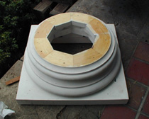
Columns such as you describe are Hollow made up of small pieces of wood. If you look up the company "Turncraft", they make Wood columns and have the load carrying capacity for columns based upon
diameter of column. It will give you a very good idea as to the load
carrying ability of your column. I will post a picture later of what your
column might look like cut in half. I happen to have one in my garage.
I had the impression that the columns were hollow and made from small turned pieces of wood.
Turncraft was a great resource, it sorta confirmed my own ideas about how much load the columns can bear, although I've decreased the load number they've provided significantly for my own application.
What this means for me is a messy weekend stripping paint off the columns and trying to fix any damage, hmmm I can almost smell the epoxy now. But at least I most likely do not need to replace.
BTW does anyone know where to get Dutchman clamps or permanent band clamps?
I'll post the pics soon, the wife is watching the bloody Tyra show and apparently that's more important ;-)
I love architects.
Zig,
If your contemplating restoration/renovation the building department will probably hold you to the current code and that probably means uplift resolution on your column assembly. I do these details all the time for work and typically use 2 approaches:
1. 4x4 wood post core – With this approach you can have simple Simpson connectors at the base and top of the wood 4x4 post to counter uplift forces. If you are on a masonry/concrete plinth you will need to install an epoxy anchored elevated post base (elevated so the post does not absorb moisture from the concrete and prematurely rot) at the bottom of the assembly. At the top of the assembly, depending on the existing framing either a Simpson post cap or a Simpson strap will do. This assembly requires that you order your new columns (I’m assuming you are replacing them) split.
2. Cable core – If you are keeping your existing columns they will be hollow at the core. For this detail I have used aircraft cable epoxy anchored at the concrete/masonryplinth and with an “eye” lagged into the existing framing at the top. Tightening the assembly is the tricky part and a come-along will help there.
A few notes on columns:
New wood columns are not like the ones from 50 years ago. The new fast-growth lumber tends to rot quickly (just a year) if the columns are not installed correctly. Order them in redwood with lock-joint construction and asphaltum treaded cores.
If you are placing the columns on a concrete/masonry plinth order new columns with aluminum plinths to separate the wood from the concrete.
Ventilation and flashing are the key to keeping wood columns around. Make sure you review the manufacturer’s venting and flashing details and follow them exactly. Have a metal shop make you up copper flashing caps and drill vent holes in the tops under the beam to allow ventilation (the aluminum plinth will have ventilation openings).
I prefer columns from Harman Sanders. Their columns have the nicest details and best looking entasis. Hartman Sanders are expensive. Somerset is my second choice.
Both Harman Sanders and Somerset make cast columns (Duracast) that feel like real wood columns (not the thin fiberglass junk) that are a preferred solution for outdoor columns but at lengths less than 8’ they are hard to come by.
Read up on column proportions (entasis is 1/3 total height) and don’t cut the shaft to a point that the vertical section of the entasis gets too short – the columns will look bad.
You can also use fiberglass columns. i know it seems unpure but the strength is tremendous compared to wood and once painted they look like glossed painted wood anyways, no rot ever.
Also, for code you are going to need to add more than 400# for the live load.
Not knowing exactly where you are and what your code requires, I am just making conservative guesses on your live load:
50#/sf
19'x8.5'
=
8,075#
Columns @ Corners,
Each column's load = 2020#
threshold,
I can't really buy new columns, my cash supply is pretty thin, that's one of the reason why I want to restore my old columns.
I've looked into the building codes and as long as I'm not removing anything I'm ok. I may need to sister an extra joist or two to the underside but then again I may not.
Also how do I go about making that "Cable Core" support thing are there any reference documents you know of?
crowbert,
I think your calcs might be more accurate than mine, I forgot to add snow load to my load calcs.
Just a question though, there are five points supporting this porch, the three columns and 2 wall outcroppings supporting this porch (the outcrops and 2 of the columns are at the corners.
Does this mean I can divide the total load, 8075 lbs by 5?
Nope,
Draw your deck.
Divide span in half from existing building to column line.
Divide column half in quarters.
The columns on the end support a quarter each (or 1/8th the total load) and the one column in the center supports two quarters (or 1/4 the total load).
The ledger attached to the building supports a uniform load (as opposed to point loads, which are the columns) which is 1/2 the span (either 4.25' or 9.5' in your case) times the #/ft. (uniform loads are measured in #/linear foot, so its 1/2 span x 1' wide)
Hope that helps more than it hurt.
If they are not going to hold you to uplift I wouldn’t worry too much about it. You can get everything at Home Depot and the only specialty tool is a cable crimper (I have the inexpensive Home Depot version and it works just fine – the nice stage set ones are big bucks). Pick up some stainless aircraft cable, a stainless steel lag-end eyebolt for attaching to the framing above, a stainless steel threaded eyebolt at least 4 inches long, a Simpson epoxy anchor kit (rent a hammer drill if you don’t have one) and some crimps for the aircraft cable.
As for the setup, just imagine the cable running vertically through the center of the column with an eyebolt embedded in the concrete base at the bottom and the other lagged to a joist of solid blocking above the column. If you can lag the upper eyebolt in a foot or so above the top of the column even better – more room to pull it tight. The best way I know if to pull it tight it to get everything setup and have someone ready with the crimping tool. Attach a come-along to the end of the cable and anchor it back to the ground then use the come-along to tighten the cable and crimp it off.
thanks crowbert,
Based on your input the centre column will take more load than the other columns, I suppose that explains why it looks like the centre column is bowing out a bit radially from its centre and has alot of vertical cracks all concentrated around its middle.
threshold,
so what you're proposing is that I link the porch roof to the column pedestal? Won't that create more downward force on the column?
I'm thinking of clamping horizontally around the radius of the column at the centre of the column's span, the other two columns seem to have some sort of permanent metal bracing or clamps wound horizontally around their radii in the middle of their spans. Could this be indicative of something?
BTW the pics are MIA until I get home.
it's indicative of stresses that are too high for the individual sections (staves) of wood making the column. each stave is individually deflecting and separating from the adjacent staves.
adding the tension ring around the column at the midpoint is a good engineering solution to keep the staves from deflecting; whether it is a good architectural solution i'll leave to you.
this is probably what you have....right?
I'm talking about meeting the uplift requirements of current building codes. You don't need to tighten it so much that you are introducing load on the columns but you do want it snug.
el....you been in my garage?
alrightly I've posted to pics to my flickr account...ooooo I feel so modern now that I have a flickr account.
here's the link:
http://www.flickr.com/photos/26482236@N08/
The photo descriptions are:
number 1 is the entire front of the house,
#4 is the left column,
#s 5 to 9 are the centre column,
#10 and #11 are close ups of the left column, including the tension ring around the column,
#s 12, 13 and 15 are close ups of the centre column (#12 shows the vertical cracks clearly, note that these are located on the side of the column facing the outdoors)
#14 just shows the slope of the porch ceiling
snook - yeah, i took the red pill...
Block this user
Are you sure you want to block this user and hide all related comments throughout the site?
Archinect
This is your first comment on Archinect. Your comment will be visible once approved.