How do you get a contractor to build a complex curve (spline)? How do you document a complex curve within a CD set. I know this has been done forever but I don't know how to do this. I have discussed this shortly in the office with a co-worker and have come up with two solutions already which might just do the trick but was wondering how some of you might approach this problem in your own work.
Just to clarify before going into some potential solutions this geometry is a simple vertical extrusion, not a double curved surface, and it double backs creating an enclosure in plan but, never intersects itself. So it seemed pretty simple at least in the design stage. And it is an interior construction. No surveyor to mark out radius +500'.
Some of the potential ways of documenting this:
1.
A. Subdivide this curve into many arcs.
B. Locate the beginning and ending points of the arc.
D. Draw a straight line between these two points
E. Give the dimension between the mid-point of the straight line and the vertex of the arc, thus describing the geometry. The contractor could then place two points of multiple arcs.
Can this create some unwanted seams in the surface?
2.
A. Create a datum possibly a column line.
B. Subdivide datum into 6" lengths
C. Run dimensions from datum to curve
If number two were the case the contractor would probably kill you, I only assume.
If anyone has any guidelines or tips that would be great,
describe the general geometry in the way you laid out in scenario 1 and make a note on the drawings that you will provide any necessary data files that are more explicit during the bidding (if they want them then) or in the shop drawing process. be prepared to provide these data files during bidding if someone wants them.
sort of crosses the line because usually archs don't want to be held responsible for dimensions, but this line is being crossed all the time these days.
second mdler. you don't have to get too explicit in your arch drawings. just give them a starting dimension off a column line and a radius (even if it is large) and let them run with it. this is easily done if you're working with a big contractor. if it's a smaller residential job, you may have to get more creative in you explanation.
I've seen contractors using GPS layout systems recently that would handle this. I don't know the details of how they work, but it comes down to a guy on the slab with a little handheld device that beeps or lights up or something when he crosses a layout line. He marks a series of points, then connects the dots with a chalk line (or something). No measuring involved, but he does lean heavily on the digital files provided to him.
That sounds like a reasonable way of going about this and just making sure the the spline is broken into manageable arcs that have a fair sense of continuity.
The template sounds intriguing and fun I don't know how my bosses would feel about it but will bring it up. Issues of Liability even though it is coming out 1 to 1 from what we have drawn. Is the contractor responsible for this or the architect?
J
The geometry is strictly a spline. In the process of CD's we thought one way of going about it was to redraw it using arcs there is just some poor continuity between them which makes me nervous.
Setting up an actual grid over the wall is much better than what i laid out in scenario 2.
mdler or jafidler
Can you describe what you are talking about with the lasers or give me something more to go on to research this.
Thanks again.
----------
As far as the actual materials of the wall... So far the partition is going to be a base of flexible runner built up out 2.5" stud, 1/4" flex MDF, 1/4" gyp. bd. and a metal cladding.
outside to in
Metal panel cladding (connection not determined) - 2x 1/4" gyp. board - 1x 1/4" flex mdf (for nailing if necessary) - stud and runner - 2x 1/4" gyp. bd. - paint
Once we know who the contractor is going to be there will definitely be more discussion but we have the go ahead from the client while they make final decisions on which contractor to use.
i was alluding to using gps coordinates and handheld laser measuring devices. really though most of this is taken care of on the construction side. it may be worth talking to your contractor about the process if you have concerns or are just curious, but you do not have to be ultra-specific in your drawings. constructing curves is standard practice. just be sure you are dimensioning accurately and that everything is coordinated with your other disciplines, and it shouldn't be a problem.
If it is small enough, the absolute best method is simply to plot out full-size templates and tape them together. It will have a slightly larger tolerance than marking out every 6" point, but welcome to construction. In the end it will come out alright.
We've had very positive results with this method with our contractors. They loooooove having you come over and tape down something they can build right on top of.
I share OF's concerns you gotta be able to draw it
look at the drawings of Carme Pinos, Enric Mirralles or Flores|Prats - its always easier to have a 90 degree reference to work from. It might also be helpful to indicate the cuts needed for the framing for the gyp board
a little of topic...
in my personal work, and it's creeping into the office, not only am i eliminating all curved surfaces (unless it's necc. for drainage/struct) but apparently i've removed all non-90 degree cuts. co workers think i'm nutty, but the contractors love it.
on a small project we layed out a 1' grid. the structural engineer had angled steel tubes along a spline curve that were tilted in to make a cone. we gave the contractor the top and bottom curve they placed the steel posts draped a metal lathe and plastered both sides. it turned out to be more complex for us to design than for them to build.
holz - yeah that's a tad interesting. Similarly i find i limit myself to only one curve and i usually make it BIG or internal. But cuts aren't as bad...but they might as well be. I tell them how many blocks per course (including 1/2 course)
i'm confronted with a similar problem in trying to describe complex curving stair(s), not free-form, but hard to describe with individual radii, resulting in a double-curving surface on the underside.
what is the convention in europe? (contractors are german, so they should be good at it).
does anyone have images to post or documents to email as a good example?
o d b's suggestion may have been overlooked, and I think it applies in lots of situations: ask the guy(s) who are doing the work which information would be most helpful to them. It goes in the "successful communication is key" box.
Yea we just used a big template plot. It was just the most strait-forward solution for small applications.
I do dream of a day when you can send 3d drawings out to fabrication shops and contractors and lazers and robots assemble everything to the millimeter.
mmm. robots.
holz. I so want to have an argument with you right now.
A history of this problem and its solutions, decade by decade, would be an interesting read. After all, Gaudi and Mendelsohn (naming just two) faced the same puzzle -- although both drawing and construction methods varied somewhat from today's !
I've encountered this problem before too. I was heavily involved in the design of a curved screen wall at the top of the roof of a sky scraper. Several of the centers of the rotations were well outside the roof plan, in some imaginary location floating 600 feet in the air.
I'm not sure exactly how they built it all, though I think a lot of it had to do with having the steel fabricator work out the exact piece dimensions, and then the contractor really only needed to properly locate the column piers. From there, they erected the structure as usual.
OK, as an aspring Architect and working at a mainly structural firm, let me say this:
ARCHITECTS! RATIONALIZE YOUR GEOMETRY!
Not only is it professionally irresponsible, it doesn't exactly do wonders for architects' reputation. Not everyone has to be Frank Gehry (and frankly not all of us have the reputation or the tools that he/his firm uses). Especially with curves, there are ways to geometrically describe it, rather than saying something like "look at the model" or worse "look at that rendering." While, I'm a fan of generative geometry, complex geometry, and etc, there has to be an intelligence behind that. As architects, we specify the geometry; we don't let models and drawings speak for us. Even if it was created with complex algorithms, parametrics, or on some geometric whim, at the end of the day, you have to simplify and rationalize in the most effective way possible to communicate it for construction.
That also means, not too much information. I ABSOLUTELY hate when someone "describes" the geometry with 3+ constraints, when 2 constraints would've defined it. The problem? There is always one constraint that is rounded up/down/irrational fraction (or something ridiculous), and sometimes it isn't clear what is the DEFINING constraint, and what is the resultant.
The choice between rational and free-form geometries is as much a matter of preferred theoretical stance and/or artistic expression as ever, but it could be argued that we now have the digital tools to realize much more easily whatever forms the designer chooses -- don't we ? A large-format plotter makes mincemeat of whatever full-size templating problem we might have -- no one need ever again look for a centerpoint on site to swing a 100-foot arc. A scaled drawing of the template, in place on the plan (or elevation), with the measurements and locations of fixed points indicated and readily transferable to the full-scale situation, ought to take the curse off of any forms (in a single plane, at least) that the architect can throw at the contractors. No ?
So, despite the apparent loss of skilled craftsmanship in some quarters, our digital media have to a great extent made up the difference, with an improvement in efficiency overall to boot. What am I missing ?
If it always went from the architect straight to the fabricators, there would be less of an issue. But on a normal project, its going through many different hands. So, IN DESIGN, yes it is a choice between rational and free-form geometries. For DOCUMENTATION, it is not a choice, it is our responsibility to document the geometry effectively (regardless of how that geometry was generated). I'm all for pushing the advancement of deliverables and fabrication/construction processes.
But unless the architect is prepared to push that process for that particular project and is active in it, it is just theoretical bullshit to justify letting some software speak for your design (and once again giving up our responsibilities for someone else to take care of it). This involves not only technology, but altering contractual obligations, liability, ownership of methods and means, and beyond. Not that there aren't those doing this already.
But if you're doing this kind of design, and not backing that shit up? Please don't do it half-assed.
Oct 28, 09 3:44 pm ·
·
Block this user
Are you sure you want to block this user and hide all related comments throughout the site?
Archinect
This is your first comment on Archinect. Your comment will be visible once approved.

Complex Curves / Construction Documents
How do you get a contractor to build a complex curve (spline)? How do you document a complex curve within a CD set. I know this has been done forever but I don't know how to do this. I have discussed this shortly in the office with a co-worker and have come up with two solutions already which might just do the trick but was wondering how some of you might approach this problem in your own work.
Just to clarify before going into some potential solutions this geometry is a simple vertical extrusion, not a double curved surface, and it double backs creating an enclosure in plan but, never intersects itself. So it seemed pretty simple at least in the design stage. And it is an interior construction. No surveyor to mark out radius +500'.
Some of the potential ways of documenting this:
1.
A. Subdivide this curve into many arcs.
B. Locate the beginning and ending points of the arc.
D. Draw a straight line between these two points
E. Give the dimension between the mid-point of the straight line and the vertex of the arc, thus describing the geometry. The contractor could then place two points of multiple arcs.
Can this create some unwanted seams in the surface?
2.
A. Create a datum possibly a column line.
B. Subdivide datum into 6" lengths
C. Run dimensions from datum to curve
If number two were the case the contractor would probably kill you, I only assume.
If anyone has any guidelines or tips that would be great,
thanks in advance.
this sounds like a job for LASERS!!!!!!!!!!!!!!!!!!!!!
describe the general geometry in the way you laid out in scenario 1 and make a note on the drawings that you will provide any necessary data files that are more explicit during the bidding (if they want them then) or in the shop drawing process. be prepared to provide these data files during bidding if someone wants them.
sort of crosses the line because usually archs don't want to be held responsible for dimensions, but this line is being crossed all the time these days.
if they're not interested in a data file, we've plotted a full-size template (in many pieces, obviously) before.
I once spent the better part of a day trying to explain how to draw an ellipse to a contractor.
second mdler. you don't have to get too explicit in your arch drawings. just give them a starting dimension off a column line and a radius (even if it is large) and let them run with it. this is easily done if you're working with a big contractor. if it's a smaller residential job, you may have to get more creative in you explanation.
why not ask the contractor what he thinks which technique would work best in the field
I've seen contractors using GPS layout systems recently that would handle this. I don't know the details of how they work, but it comes down to a guy on the slab with a little handheld device that beeps or lights up or something when he crosses a layout line. He marks a series of points, then connects the dots with a chalk line (or something). No measuring involved, but he does lean heavily on the digital files provided to him.
Thanks for the response everyone.
Steven
That sounds like a reasonable way of going about this and just making sure the the spline is broken into manageable arcs that have a fair sense of continuity.
The template sounds intriguing and fun I don't know how my bosses would feel about it but will bring it up. Issues of Liability even though it is coming out 1 to 1 from what we have drawn. Is the contractor responsible for this or the architect?
J
The geometry is strictly a spline. In the process of CD's we thought one way of going about it was to redraw it using arcs there is just some poor continuity between them which makes me nervous.
Setting up an actual grid over the wall is much better than what i laid out in scenario 2.
mdler or jafidler
Can you describe what you are talking about with the lasers or give me something more to go on to research this.
Thanks again.
----------
As far as the actual materials of the wall... So far the partition is going to be a base of flexible runner built up out 2.5" stud, 1/4" flex MDF, 1/4" gyp. bd. and a metal cladding.
outside to in
Metal panel cladding (connection not determined) - 2x 1/4" gyp. board - 1x 1/4" flex mdf (for nailing if necessary) - stud and runner - 2x 1/4" gyp. bd. - paint
Once we know who the contractor is going to be there will definitely be more discussion but we have the go ahead from the client while they make final decisions on which contractor to use.
i was alluding to using gps coordinates and handheld laser measuring devices. really though most of this is taken care of on the construction side. it may be worth talking to your contractor about the process if you have concerns or are just curious, but you do not have to be ultra-specific in your drawings. constructing curves is standard practice. just be sure you are dimensioning accurately and that everything is coordinated with your other disciplines, and it shouldn't be a problem.
Second Steven Ward.
If it is small enough, the absolute best method is simply to plot out full-size templates and tape them together. It will have a slightly larger tolerance than marking out every 6" point, but welcome to construction. In the end it will come out alright.
We've had very positive results with this method with our contractors. They loooooove having you come over and tape down something they can build right on top of.
I share OF's concerns you gotta be able to draw it
look at the drawings of Carme Pinos, Enric Mirralles or Flores|Prats - its always easier to have a 90 degree reference to work from. It might also be helpful to indicate the cuts needed for the framing for the gyp board
a little of topic...
in my personal work, and it's creeping into the office, not only am i eliminating all curved surfaces (unless it's necc. for drainage/struct) but apparently i've removed all non-90 degree cuts. co workers think i'm nutty, but the contractors love it.
right angles are the wave of the future.
hmm, i'm mostly curious about the layer of mdf plus the layer of gyp ... any reason not to use just one or the other? how big is this thing?
on a small project we layed out a 1' grid. the structural engineer had angled steel tubes along a spline curve that were tilted in to make a cone. we gave the contractor the top and bottom curve they placed the steel posts draped a metal lathe and plastered both sides. it turned out to be more complex for us to design than for them to build.
holz - yeah that's a tad interesting. Similarly i find i limit myself to only one curve and i usually make it BIG or internal. But cuts aren't as bad...but they might as well be. I tell them how many blocks per course (including 1/2 course)
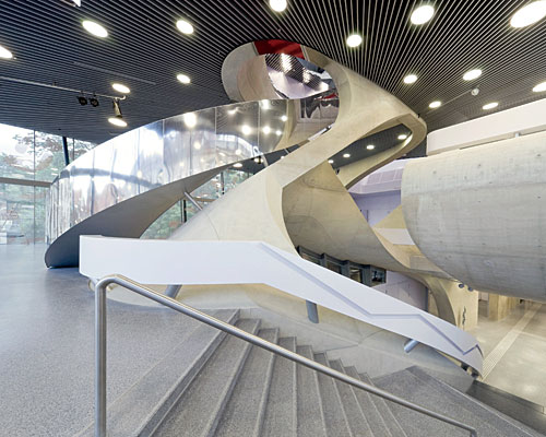
i'm confronted with a similar problem in trying to describe complex curving stair(s), not free-form, but hard to describe with individual radii, resulting in a double-curving surface on the underside.
what is the convention in europe? (contractors are german, so they should be good at it).
does anyone have images to post or documents to email as a good example?
o d b's suggestion may have been overlooked, and I think it applies in lots of situations: ask the guy(s) who are doing the work which information would be most helpful to them. It goes in the "successful communication is key" box.
thanks for the suggestion, however, this project is in the design development phase. there are no contractors on board yet.
it's not quite as extreme, but how would you document this beast?
how do you post images on here?
do i have to post enough to be able to?
nero, they have to be online already - either in the images section here or on flickr, shutterfly, etc.
once you've got an image online, use the code in gray below.
this is similar to method 2 for an interior project
sorry, but i am too dumb to figure the codes to embed this pix...
http://picasaweb.google.com/niro3000/MyPictures#5397474482193006306
if possible can someone embed the pix and show me the code?
depends on the size... if its a standard 2x4 wall, just cnc the top and bottom plates with 3/4 ply..double it up...
or make a paper template... with tick marks so you can line them up a-a, b-b,etc
ahhh..... i just read the first few posts then i posted.... as for stairs..hmmmm
Proxy,
If you're still around, please let us know what your final soultion was!
Yea we just used a big template plot. It was just the most strait-forward solution for small applications.
I do dream of a day when you can send 3d drawings out to fabrication shops and contractors and lazers and robots assemble everything to the millimeter.
mmm. robots.
holz. I so want to have an argument with you right now.
A history of this problem and its solutions, decade by decade, would be an interesting read. After all, Gaudi and Mendelsohn (naming just two) faced the same puzzle -- although both drawing and construction methods varied somewhat from today's !
I've encountered this problem before too. I was heavily involved in the design of a curved screen wall at the top of the roof of a sky scraper. Several of the centers of the rotations were well outside the roof plan, in some imaginary location floating 600 feet in the air.
I'm not sure exactly how they built it all, though I think a lot of it had to do with having the steel fabricator work out the exact piece dimensions, and then the contractor really only needed to properly locate the column piers. From there, they erected the structure as usual.
OK, as an aspring Architect and working at a mainly structural firm, let me say this:
ARCHITECTS! RATIONALIZE YOUR GEOMETRY!
Not only is it professionally irresponsible, it doesn't exactly do wonders for architects' reputation. Not everyone has to be Frank Gehry (and frankly not all of us have the reputation or the tools that he/his firm uses). Especially with curves, there are ways to geometrically describe it, rather than saying something like "look at the model" or worse "look at that rendering." While, I'm a fan of generative geometry, complex geometry, and etc, there has to be an intelligence behind that. As architects, we specify the geometry; we don't let models and drawings speak for us. Even if it was created with complex algorithms, parametrics, or on some geometric whim, at the end of the day, you have to simplify and rationalize in the most effective way possible to communicate it for construction.
That also means, not too much information. I ABSOLUTELY hate when someone "describes" the geometry with 3+ constraints, when 2 constraints would've defined it. The problem? There is always one constraint that is rounded up/down/irrational fraction (or something ridiculous), and sometimes it isn't clear what is the DEFINING constraint, and what is the resultant.
Sorry, rant over.
The choice between rational and free-form geometries is as much a matter of preferred theoretical stance and/or artistic expression as ever, but it could be argued that we now have the digital tools to realize much more easily whatever forms the designer chooses -- don't we ? A large-format plotter makes mincemeat of whatever full-size templating problem we might have -- no one need ever again look for a centerpoint on site to swing a 100-foot arc. A scaled drawing of the template, in place on the plan (or elevation), with the measurements and locations of fixed points indicated and readily transferable to the full-scale situation, ought to take the curse off of any forms (in a single plane, at least) that the architect can throw at the contractors. No ?
So, despite the apparent loss of skilled craftsmanship in some quarters, our digital media have to a great extent made up the difference, with an improvement in efficiency overall to boot. What am I missing ?
If it always went from the architect straight to the fabricators, there would be less of an issue. But on a normal project, its going through many different hands. So, IN DESIGN, yes it is a choice between rational and free-form geometries. For DOCUMENTATION, it is not a choice, it is our responsibility to document the geometry effectively (regardless of how that geometry was generated). I'm all for pushing the advancement of deliverables and fabrication/construction processes.
But unless the architect is prepared to push that process for that particular project and is active in it, it is just theoretical bullshit to justify letting some software speak for your design (and once again giving up our responsibilities for someone else to take care of it). This involves not only technology, but altering contractual obligations, liability, ownership of methods and means, and beyond. Not that there aren't those doing this already.
But if you're doing this kind of design, and not backing that shit up? Please don't do it half-assed.
Block this user
Are you sure you want to block this user and hide all related comments throughout the site?
Archinect
This is your first comment on Archinect. Your comment will be visible once approved.