The problem is called lateral torsional buckling, but it doesn't just affect cantilevers. It can be a problem in any beam that is too thin compared to its depth and its span. If you put a yardstick on its edge between two desks (or hold one end down and cantilever the other) and push down in the center, you'll feel it want to twist out to the side. That's lateral torsional buckling.
Here's an example of asymmetrical deflection at a Wright structure, the 1940 Goetsch/Winckler residence, Okemos, MI. The carport is a major extension of the main roof, supported by east and west fulcra which occur at unequal distances from its unsupported end. The second photo, taken shortly after completion (the third image is a detail from the center of the photo) clearly shows that the carport cantilever has already sagged from the horizontal, revealed by comparing its far edge with the outlines of the kitchen window. Deflection can also be seen in the (relatively recent) color image.
The house has been restored -- there was a story in an issue of "Old House Journal" in the early 'nineties (which I did not see) outlining roof work done then. But I do not believe that intervention was undertaken that was major enough to correct the roof deflection.
Restoring a serious structural problem like that in a Wright building would have to be difficult. It would likely require switching materials or increasing the depth of the framing, both of which might be unacceptable in terms of historic preservation.
The problem with Torsion is that you need to either resist the stress with the member itself, or brace it laterally to resist the loading. This generally increases member sizes. The most efficient members for dealing with torsion stresses are tube shapes, such as hollow steel sections. This is different than bending moments, which are better resisted by members with high moments of inertia, such as wide flange beams. Additionally, the connections will need to be able to resist the induced torsion.
In a cantilever, the tendency for a member to twist due to torsion is especially high, and the ability to brace the member is generally low as the member can usually only connect back to other cantilevered beams. The beams ware possible, but not ideal candidates for use as brace supports. Additionally, deflection issues will be a major concern. Cantilevers are inherently prone to vertical deflections because the member is unsupported on one of its ends. This fact, when combined with rotational deflection from torsion stresses, can result in especially high total deflections and cracking in cover materials such as masonry.
All of these issues can be designed for, but they do generally require heavier members to resist the complex stress condition.
Wright seems to have had a sort of mono-material bias with his Usonian houses; having declared that they would contain just five materials -- wood, concrete, brick, [building]paper and glass -- he was perhaps reluctant to add steel, though he had used that material from the start; there is a lot of steel in the Robie house, for instance, where it is essential to the major cantilevers of the main roof. Cost, in the early Usonians, was another factor. But the apprentices who got those houses built, usually with local labor and sometimes by seasoned builders like Harold Turner (as at the Goetsch/Winckler house), learned to sneak some steel in where it would be most effective.
If the G/W house received some steel originally, or during the roof restoration, I have not learned of it. Wright's structure for these roofs was simply three courses of 2x4s on edge, built up into a single 12" joist and tapering off at the eave to 8" and then 4" (note the stepped detail to the eave in the photo above). I assume but do not know that this is the only structure in the roof shown. How this could be sufficient for the extensive cantilever is beyond me.
By closely reading my copy of "Affordable Dreams" (Vol. VI, 1991, of the Bulletin of the Kresge Art Museum, Michigan State University, a mongraph on the Goetsch/Winckler house) I finally came upon a reference to the roof construction. To wit:
Happily, there have been no major physical changes or additions to the 1940 Goetsch-Winckler house and it remains a perfect reflection of
Wright's Usonian ideas. Like many other fifty-year-old homes, it has required numerous repairs over the years, but these have been done in
the spirit of its architect's original vision. As early as 1946, Kathrine Winckler wrote to Eugene Masselink, Wright's assistant, that the outside of
the house "is beginning to look a little shabby. The wood is weathering rather badly -- some parts are dark and others light. We don't know just
what to do about it." From early on, the cantilever over the carport began to sag. In 1957 this roof was reframed and a four-inch steel channel was
added. In 1969, the roof under the northeast clerestory received additional framing support and the siding was revarnished. Most recently,
in 1989, new roofing was applied in an effort to solve the chronic problems of Wright's flat roof design. [p xvi]
[Note to the above paragraph]
Interestingly, while working on this latest repair, Ann Arbor designer and contractor Don Price discovered a number of discrepancies between the
original blueprints and the actual construction. Among the most surprising of these discrepancies was the presence of a large steel beam in the
cantilever roof above the carport. Since Wright's plans are unclear as to the amount of steel that would have been needed to support the
cantilever, contractor Harold Turner appears to have made a decision to include the beam. See Don Price, "Cantilever Tales: An Old Modern Gets a
New Roof," Old House Journal. XVIU, no. 3 (May/June 1990): 42-47. The major restorations at this time included replacing the old roof with a new
one, fixing the sag in the carport cantilever, and reinforcing and realigning the windows and brick planter on the southwest exterior wall. The original
flat skylights were replaced with domed ones and a new type of membrane roof replaced the old one of felt, tar, and gravel. In addition,
the upper roof was repitched to prevent it from draining onto the lower roof. Because of a limited budget, the owner decided against replacing the
trellises and fixing the brick lanai wall that had begun to deflect and crack.
I am now more intent than ever on seeing that issue of the Old House Journal. Photos may reveal in which direction the major and secondary steel members run -- and where they are placed. From the last photo, above, one would surmise that a beam might have been extended from the lower roof on the left, passing through the chimney mass and into the carport roof, where it could have supported longitudinal joists. A mighty tie-down at the corner of the building nearest the camera, through the clerestory glass and the wall and into the brick foundation, would have constituted the counterbalance to that heavily loaded cantilever.
Can anyone suggest another strategy, based on what can be seen in these photos ?
The relevant corner, of clerestory and wall, is seen in this interior photo, at the point furthest away from the camera. The glass is mitered at the change of plane; the tie-down (if present) would presumably pass through the first mullion to the right of that corner.
Ahh so this sheds some light on the mystery. It is hard to imagine an all wood solution for this length of cantilever, so the steel makes perfect sense. An LVL or PSL under just its own weight will have trouble cantilevering that distance without deflection problems. During Wright's time these options were not even available.
If I was framing this up new, I would look into running a diagonal cantilever out to that corner. and having other members running perpendicular with the short span (up and down in the plan view). Of course this would require coordination to keep the elevations of the framing in the correct plane.
However it was framed, to do it right (and avoid the numerous repairs this building has had to undergo) you would need to use a variety of moment connections and tie backs. The specific framing layout is difficult for me to predict based on limited information I can get out of the photographs.
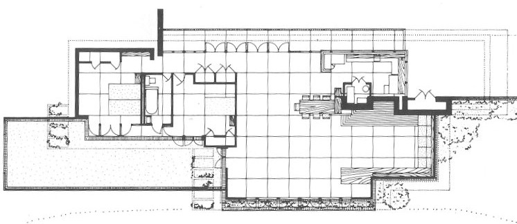
That's the plan. The module is a 4' square. The carport roof is indicated with dotted lines at upper right. The roof at the plane which includes the carport is not present in a rectangle which starts at the lower left corner of the main space, and extends 28' to the right and 16' "up" -- at the face of the chimney mass. Here the higher roof rests on a continuous band of clerestory glass. So, a diagonal beam within the lower roof plane could reach as far as the root of the built-in table at the bottom of the plan -- a nice improvement over my suggestion.
Yup -- I agree. At least, in his orthogonal work. The diagonals are all implied; don't you love the diagonal march of rectangles in this sublime plan ?
I remember asking one of my design instructors whether it mattered that the plan looked good on paper, as long as it worked in fact. He said it did. I soon enough came around. . .
Hey no arguement here, FLW was an adept archtitect, but clearly he didn't fully understand structural design, or he wouldn't have attempted a double cantilevered structure out of wood with such stringent depth requirements.
It seems that way to me. (In fairness it is possible that Wright saw steel in this roof from the start; I have not seen the original drawings.) The Fallingwater double cantilevers take the cake, and in heavier materials to boot; a clever intervention five years ago may have prevented total failure.
Apr 6, 09 1:17 pm ·
·
Block this user
Are you sure you want to block this user and hide all related comments throughout the site?
Archinect
This is your first comment on Archinect. Your comment will be visible once approved.

Torsion
Can anyone explain why a cantilever is bad for torsion? . I am writing an essay on some of the engineering of wrights work.
don't mean to be a dick, but isn't it pretty obvious why a cantilever is weak in torsion?
The problem is called lateral torsional buckling, but it doesn't just affect cantilevers. It can be a problem in any beam that is too thin compared to its depth and its span. If you put a yardstick on its edge between two desks (or hold one end down and cantilever the other) and push down in the center, you'll feel it want to twist out to the side. That's lateral torsional buckling.
are we talking about torsion or moment?
oh boy, it's been a while since structures class... torsion and moment are not the same right?
if i have the jist right, torsion occurs within plane, whereas moment refers to a rotation around an axis perpendicular to plane?
torsion is moment about the long axis (twist).
i can't think of any torsion related architectural implications in wright's work.
a cantilever maximum bending moment is perpendicular at the piece projecting out, and is a torsional moment about the beam long axis
Here's an example of asymmetrical deflection at a Wright structure, the 1940 Goetsch/Winckler residence, Okemos, MI. The carport is a major extension of the main roof, supported by east and west fulcra which occur at unequal distances from its unsupported end. The second photo, taken shortly after completion (the third image is a detail from the center of the photo) clearly shows that the carport cantilever has already sagged from the horizontal, revealed by comparing its far edge with the outlines of the kitchen window. Deflection can also be seen in the (relatively recent) color image.


they fixed it?
The house has been restored -- there was a story in an issue of "Old House Journal" in the early 'nineties (which I did not see) outlining roof work done then. But I do not believe that intervention was undertaken that was major enough to correct the roof deflection.
Restoring a serious structural problem like that in a Wright building would have to be difficult. It would likely require switching materials or increasing the depth of the framing, both of which might be unacceptable in terms of historic preservation.
The problem with Torsion is that you need to either resist the stress with the member itself, or brace it laterally to resist the loading. This generally increases member sizes. The most efficient members for dealing with torsion stresses are tube shapes, such as hollow steel sections. This is different than bending moments, which are better resisted by members with high moments of inertia, such as wide flange beams. Additionally, the connections will need to be able to resist the induced torsion.
In a cantilever, the tendency for a member to twist due to torsion is especially high, and the ability to brace the member is generally low as the member can usually only connect back to other cantilevered beams. The beams ware possible, but not ideal candidates for use as brace supports. Additionally, deflection issues will be a major concern. Cantilevers are inherently prone to vertical deflections because the member is unsupported on one of its ends. This fact, when combined with rotational deflection from torsion stresses, can result in especially high total deflections and cracking in cover materials such as masonry.
All of these issues can be designed for, but they do generally require heavier members to resist the complex stress condition.
Wright seems to have had a sort of mono-material bias with his Usonian houses; having declared that they would contain just five materials -- wood, concrete, brick, [building]paper and glass -- he was perhaps reluctant to add steel, though he had used that material from the start; there is a lot of steel in the Robie house, for instance, where it is essential to the major cantilevers of the main roof. Cost, in the early Usonians, was another factor. But the apprentices who got those houses built, usually with local labor and sometimes by seasoned builders like Harold Turner (as at the Goetsch/Winckler house), learned to sneak some steel in where it would be most effective.
If the G/W house received some steel originally, or during the roof restoration, I have not learned of it. Wright's structure for these roofs was simply three courses of 2x4s on edge, built up into a single 12" joist and tapering off at the eave to 8" and then 4" (note the stepped detail to the eave in the photo above). I assume but do not know that this is the only structure in the roof shown. How this could be sufficient for the extensive cantilever is beyond me.
Another view; carport cantilever at right

Great insight into this one, SDR. I too question how this thing survives, I wonder how it responds to snow and wind loads?
Yes, I forgot to add "the icing on the cake": most of these houses are built in snow country. The man had balls, I'll give him that. . .!
By closely reading my copy of "Affordable Dreams" (Vol. VI, 1991, of the Bulletin of the Kresge Art Museum, Michigan State University, a mongraph on the Goetsch/Winckler house) I finally came upon a reference to the roof construction. To wit:
Happily, there have been no major physical changes or additions to the 1940 Goetsch-Winckler house and it remains a perfect reflection of
Wright's Usonian ideas. Like many other fifty-year-old homes, it has required numerous repairs over the years, but these have been done in
the spirit of its architect's original vision. As early as 1946, Kathrine Winckler wrote to Eugene Masselink, Wright's assistant, that the outside of
the house "is beginning to look a little shabby. The wood is weathering rather badly -- some parts are dark and others light. We don't know just
what to do about it." From early on, the cantilever over the carport began to sag. In 1957 this roof was reframed and a four-inch steel channel was
added. In 1969, the roof under the northeast clerestory received additional framing support and the siding was revarnished. Most recently,
in 1989, new roofing was applied in an effort to solve the chronic problems of Wright's flat roof design. [p xvi]
[Note to the above paragraph]
Interestingly, while working on this latest repair, Ann Arbor designer and contractor Don Price discovered a number of discrepancies between the
original blueprints and the actual construction. Among the most surprising of these discrepancies was the presence of a large steel beam in the
cantilever roof above the carport. Since Wright's plans are unclear as to the amount of steel that would have been needed to support the
cantilever, contractor Harold Turner appears to have made a decision to include the beam. See Don Price, "Cantilever Tales: An Old Modern Gets a
New Roof," Old House Journal. XVIU, no. 3 (May/June 1990): 42-47. The major restorations at this time included replacing the old roof with a new
one, fixing the sag in the carport cantilever, and reinforcing and realigning the windows and brick planter on the southwest exterior wall. The original
flat skylights were replaced with domed ones and a new type of membrane roof replaced the old one of felt, tar, and gravel. In addition,
the upper roof was repitched to prevent it from draining onto the lower roof. Because of a limited budget, the owner decided against replacing the
trellises and fixing the brick lanai wall that had begun to deflect and crack.
I am now more intent than ever on seeing that issue of the Old House Journal. Photos may reveal in which direction the major and secondary steel members run -- and where they are placed. From the last photo, above, one would surmise that a beam might have been extended from the lower roof on the left, passing through the chimney mass and into the carport roof, where it could have supported longitudinal joists. A mighty tie-down at the corner of the building nearest the camera, through the clerestory glass and the wall and into the brick foundation, would have constituted the counterbalance to that heavily loaded cantilever.

Can anyone suggest another strategy, based on what can be seen in these photos ?
The relevant corner, of clerestory and wall, is seen in this interior photo, at the point furthest away from the camera. The glass is mitered at the change of plane; the tie-down (if present) would presumably pass through the first mullion to the right of that corner.
Ahh so this sheds some light on the mystery. It is hard to imagine an all wood solution for this length of cantilever, so the steel makes perfect sense. An LVL or PSL under just its own weight will have trouble cantilevering that distance without deflection problems. During Wright's time these options were not even available.
I found this link to a plan
If I was framing this up new, I would look into running a diagonal cantilever out to that corner. and having other members running perpendicular with the short span (up and down in the plan view). Of course this would require coordination to keep the elevations of the framing in the correct plane.
However it was framed, to do it right (and avoid the numerous repairs this building has had to undergo) you would need to use a variety of moment connections and tie backs. The specific framing layout is difficult for me to predict based on limited information I can get out of the photographs.
That's the plan. The module is a 4' square. The carport roof is indicated with dotted lines at upper right. The roof at the plane which includes the carport is not present in a rectangle which starts at the lower left corner of the main space, and extends 28' to the right and 16' "up" -- at the face of the chimney mass. Here the higher roof rests on a continuous band of clerestory glass. So, a diagonal beam within the lower roof plane could reach as far as the root of the built-in table at the bottom of the plan -- a nice improvement over my suggestion.
somehow i have my doubts flw would accept a diagonal beam, even if you never saw it.
Yup -- I agree. At least, in his orthogonal work. The diagonals are all implied; don't you love the diagonal march of rectangles in this sublime plan ?
I remember asking one of my design instructors whether it mattered that the plan looked good on paper, as long as it worked in fact. He said it did. I soon enough came around. . .
Hey no arguement here, FLW was an adept archtitect, but clearly he didn't fully understand structural design, or he wouldn't have attempted a double cantilevered structure out of wood with such stringent depth requirements.
It seems that way to me. (In fairness it is possible that Wright saw steel in this roof from the start; I have not seen the original drawings.) The Fallingwater double cantilevers take the cake, and in heavier materials to boot; a clever intervention five years ago may have prevented total failure.
Block this user
Are you sure you want to block this user and hide all related comments throughout the site?
Archinect
This is your first comment on Archinect. Your comment will be visible once approved.