I am dealing with a GIS drawing and it's driving me crazy. The drawing is great except for the fact that the topo lines do not continue when they intersect a building/road/etc. they split, then make it a pain in the ass to go back and manually rejoin (Close) the splines into a continuous spline that would render a more accurate topo drawing and resulting 3d model...
is there a lisp script that will automatically connect the topo lines at each real-world Z value...? if so, it would make my life much easier.
Filtering out the lines from their z value proberly make a drawing that will be easier -- but there still will remain the problems with overlapping vectors. I don't think the problem with horison crossing vectors is bigger than simply closing those that has both ends crossing the horison will solve all those .. but after that the tradisional problems still remain ,that could proberly be solved for 80 pct of the remaining , by finding those where endpoints are nearest to another untill no more vectors at that hight remain, but it will be a mess, nomater if you filter all entities from max x to min x, from max y to min y and make some logic to it, it still will be a mess.
I dont use AutoCAD(not recommended) for creating 3d topos , but if you were to open your file on Rhino you could use RhinoTerrain. steps: First make sure all you contour lines have the correct z value height. then use Rhinoterrain (it wont matter that the topo lines are broken/ do not continue). The only issue is that Rhino terrain creates a triangulated mesh surface. To make this a workable surface. I then would use a surface drape (the only time I ever use this command) with settings "autospacing yes, spacing distance 3". Then new surface created by the drape becomes more workable and easier to attack(modify).--SO the best recommendation I can give you is ditch CAD for topos
many thanks for the replies but aside from applying unadulterated digital will to this file and with my current tools, looks i'm kinda out of luck.
I will be importing this file into Max which has its own terrain feature, but that's when i realized i needed to clean up my source .dwg... the resuting mesh, using Max was rubbish. Since i'm not using rhino (except for eval version) that terrain plugin won't help much :(
Eh -- now I forgot to ask about how precice the resulting mesh shuld be.
I guess there are simple way's to configure a mesh, simply by counting up the cross points in xy between a decided mesh and any underlaying mess of plines , simply by finding every point in xy where contour lines along each individual mesh lines intersect, -- there are ready made functions for that,,
Guess that would be a simple Lisp issue, also adding the z value to each found intersection can not be that much of a problem, suddenly it seem a trivial problem --- so this is a blueprint, but the mesh still will be inperfect but maybe less than the lines.
Now this morning I am sure these issues were solved a decade ago and I am sure you will be able to find applications -- I don't know how active AutoLisp fora's are but there are many other language that is used today to build AutoCAD applications , -- Point cloud is my best advise ; these are made the way I explain above, by finding intersections between difficult entities and a pre. choosen mesh in xy I would ask for such applications first. The Points sometimes are collected by random, but then it is easy to filter these, top down, left to right into a matrix that will produce a polymesh.
I agree with DifficultFix RhinoTerrian works best.
cowgirl Rhinoceros is well worth the investment and you could just leave MAX and autocad all together. student?
i wouldn't say ditch cad for topos though Rhino is the cad ;)
yeah, rhino terrain looks like a damn powerful tool.
i am a student (working on M.Arch thesis but also working full-time internship) so i can pull rhino in at the student rate:) I have actually put purchasing rhino off for far too long and just need to bite the bullet and get on the train.
...until then, looks like i'm still hunting for a lisp via corell's description.
Just tested it with AutoCAD14 and it turn out it ask lines but seem to have a bit problems with plines. Othervise loaded and strartd by typing lv , it ask for "some lines", there you just answer with c as in crossing, and select the lines with the crosing box. press enter and it even ask how dense a mesh you require --- and then it generate a mesh , look at it with vpoint and you be surprised.
If plines are filtered out, just explode them first, then they become lines. And when asked to select lines, just answer all ... Guess you know how to copy the iv.lsp and write it to a new lv.lsp --- othervise, just copy the code and paste it onto the command line.
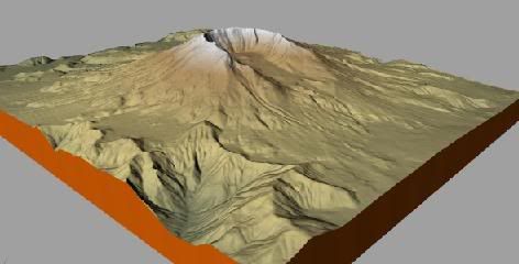
This was made with a mesh with 120 x 120 lattrice -- the defult are 12 but you can type in the mesg as you want it -- then it was smoothened by Pedit , smoot option, where I set surfu and surfv to 120 -- the two sysvars that decide the density of the smooth --- if you want varying color depending on hights that is also an option, but that is a different story.
"is there a lisp script that will automatically connect the topo lines at each real-world Z value...? if so, it would make my life much easier."
The lv.lsp mentioned above will probrtly not make your life easier, it ask some basic knowleage about AutoCAD -- that you know how to load and start an application and it don't offer the interface , only a command line dialog and no instructions - it is simply another generation ; copyright 1995 --- but forced to the limits, I guess it will deliver splendid terrain models.
if you do slices just do them along the Topo lines themselves is what i do sometimes because i like that look of cardboard cut out topo it gives clients more of an idea where the different elevation lines are and makes it easy to do 'earth work'
Anti ~ I agree about the visual appeal of the slices but isn't dammson's method made out of a solids modeling operation...? which CAN be done, but my god... the only way i can see that happening is by manually drawing each slice in section, PE (join), then extruding it to the desired thickness... the more precise (smaller slices) requires you to draw more sections... what am i missing?
i also don't mind the horizontal cardboard "stepped" type of site model either... but that still requires a lot of contour line work to get it to look decent.
per ~ I'm looking into working with your lv.lsp script... trying to figure out how to load and start an application... :D
Well -- I am a specialist explaining things so people get dizzy, but just go to the link, select all, copy it --- and when you has opened the drawing ,just copy to the command line , then you lust type lv and then the application shuld be running. Now these terrains, isn't there another way, such as drilling holes in a board, place pins with the right hight and then cover the pins with fabric, or plaster up to top of the pins, ----- maybe drill holes in a styrofoam sheet glue pins in the holes and sand down from the opposite side, untill you hit the pins -- just a suggestion.
Sorry -- I just made my mind wander -- do it by slices whatever diretion you find best , if you maneage one at the time it is just about placing some callibrating holes and move the elevation and then use Slice command to make the section -- before plotting it on the fly, maybe freeze the layer the mesh is on.
Using ucs to move the slice plane .
ok, i got the lisp to run and am trying to figure out how dense i can make the mesh for more control. seems to get errors @ 200 lines in both x and y directions but 150 is chugging right along.
K --- when you has the polymesh I suggest you trim two sysvars and then use Pedit command "smooth" option to smooth the mesh -- unless you set the two you will be back to defult 12x12 or 6x6 again after a smooth. Anyway just type surfu and ansver with up to 199 and yhen surfv and ansver up to 199 -- I think the same limit as you say are there to. But offcaurse you can say whatever density and maybe 199 is very high density.
Surfv x, surfu y, pedit, s.
I think you are quite right, point clouds was a splendid solution I think the concept is some 8-10 years old so a lot of applications must be avaible. Strange in fact, as you shuld think the order in a polymesh matrix is a better start point, but order can be computed from chaos , it's all about seting up some rules -- Lisp btw. is perfect for just that, but I guess one only realise, when seeing a recursive 3 line function turn chaos into beauty.
I know the unfolding rutine in Rhino shuld work , -- that is a rutine to unfold polymeshes into strips that shuld create the mesh put together again, but only with entities made in rhino , it don't handle meshes imported from AutoCAD. That's one reson you has to write your own unfolding app. for AutoCAD.
Oct 21, 08 7:33 pm ·
·
Block this user
Are you sure you want to block this user and hide all related comments throughout the site?
Archinect
This is your first comment on Archinect. Your comment will be visible once approved.

autocad topo lines
I am dealing with a GIS drawing and it's driving me crazy. The drawing is great except for the fact that the topo lines do not continue when they intersect a building/road/etc. they split, then make it a pain in the ass to go back and manually rejoin (Close) the splines into a continuous spline that would render a more accurate topo drawing and resulting 3d model...
is there a lisp script that will automatically connect the topo lines at each real-world Z value...? if so, it would make my life much easier.
thanks,
working with acad arch 2009
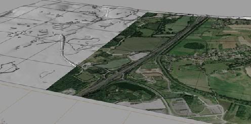
a taste of the madness:

prost!
you know - I hate that too. Drives me nuts. Worse if the contour lines aren't drawn to the horizon or with a z=0 value. But nope sorry can't help
Filtering out the lines from their z value proberly make a drawing that will be easier -- but there still will remain the problems with overlapping vectors. I don't think the problem with horison crossing vectors is bigger than simply closing those that has both ends crossing the horison will solve all those .. but after that the tradisional problems still remain ,that could proberly be solved for 80 pct of the remaining , by finding those where endpoints are nearest to another untill no more vectors at that hight remain, but it will be a mess, nomater if you filter all entities from max x to min x, from max y to min y and make some logic to it, it still will be a mess.
this can be fixed easily, right? select all, open the modify dialog box, and change the z value to 0
cant you fillet them?.........
I dont use AutoCAD(not recommended) for creating 3d topos , but if you were to open your file on Rhino you could use RhinoTerrain. steps: First make sure all you contour lines have the correct z value height. then use Rhinoterrain (it wont matter that the topo lines are broken/ do not continue). The only issue is that Rhino terrain creates a triangulated mesh surface. To make this a workable surface. I then would use a surface drape (the only time I ever use this command) with settings "autospacing yes, spacing distance 3". Then new surface created by the drape becomes more workable and easier to attack(modify).--SO the best recommendation I can give you is ditch CAD for topos
www.rhinoterrain.com
difficultfix
many thanks for the replies but aside from applying unadulterated digital will to this file and with my current tools, looks i'm kinda out of luck.
I will be importing this file into Max which has its own terrain feature, but that's when i realized i needed to clean up my source .dwg... the resuting mesh, using Max was rubbish. Since i'm not using rhino (except for eval version) that terrain plugin won't help much :(
thanks.
Eh -- now I forgot to ask about how precice the resulting mesh shuld be.
I guess there are simple way's to configure a mesh, simply by counting up the cross points in xy between a decided mesh and any underlaying mess of plines , simply by finding every point in xy where contour lines along each individual mesh lines intersect, -- there are ready made functions for that,,
Guess that would be a simple Lisp issue, also adding the z value to each found intersection can not be that much of a problem, suddenly it seem a trivial problem --- so this is a blueprint, but the mesh still will be inperfect but maybe less than the lines.
Now this morning I am sure these issues were solved a decade ago and I am sure you will be able to find applications -- I don't know how active AutoLisp fora's are but there are many other language that is used today to build AutoCAD applications , -- Point cloud is my best advise ; these are made the way I explain above, by finding intersections between difficult entities and a pre. choosen mesh in xy I would ask for such applications first. The Points sometimes are collected by random, but then it is easy to filter these, top down, left to right into a matrix that will produce a polymesh.
I agree with DifficultFix RhinoTerrian works best.
cowgirl Rhinoceros is well worth the investment and you could just leave MAX and autocad all together. student?
i wouldn't say ditch cad for topos though Rhino is the cad ;)
yeah, rhino terrain looks like a damn powerful tool.
i am a student (working on M.Arch thesis but also working full-time internship) so i can pull rhino in at the student rate:) I have actually put purchasing rhino off for far too long and just need to bite the bullet and get on the train.
...until then, looks like i'm still hunting for a lisp via corell's description.
thanks.
Hi -- it was only 5 min. of Google and the lv.lsp turned up ;
http://www.accustudio.com/data/marketplace/free/lv.lsp
Just tested it with AutoCAD14 and it turn out it ask lines but seem to have a bit problems with plines. Othervise loaded and strartd by typing lv , it ask for "some lines", there you just answer with c as in crossing, and select the lines with the crosing box. press enter and it even ask how dense a mesh you require --- and then it generate a mesh , look at it with vpoint and you be surprised.
If plines are filtered out, just explode them first, then they become lines. And when asked to select lines, just answer all ... Guess you know how to copy the iv.lsp and write it to a new lv.lsp --- othervise, just copy the code and paste it onto the command line.
This was made with a mesh with 120 x 120 lattrice -- the defult are 12 but you can type in the mesg as you want it -- then it was smoothened by Pedit , smoot option, where I set surfu and surfv to 120 -- the two sysvars that decide the density of the smooth --- if you want varying color depending on hights that is also an option, but that is a different story.
http://img515.imageshack.us/img515/7079/drawingado1.jpg
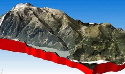
just do solid vertical slices...

"is there a lisp script that will automatically connect the topo lines at each real-world Z value...? if so, it would make my life much easier."
The lv.lsp mentioned above will probrtly not make your life easier, it ask some basic knowleage about AutoCAD -- that you know how to load and start an application and it don't offer the interface , only a command line dialog and no instructions - it is simply another generation ; copyright 1995 --- but forced to the limits, I guess it will deliver splendid terrain models.
if you do slices just do them along the Topo lines themselves is what i do sometimes because i like that look of cardboard cut out topo it gives clients more of an idea where the different elevation lines are and makes it easy to do 'earth work'
Anti ~ I agree about the visual appeal of the slices but isn't dammson's method made out of a solids modeling operation...? which CAN be done, but my god... the only way i can see that happening is by manually drawing each slice in section, PE (join), then extruding it to the desired thickness... the more precise (smaller slices) requires you to draw more sections... what am i missing?
i also don't mind the horizontal cardboard "stepped" type of site model either... but that still requires a lot of contour line work to get it to look decent.
per ~ I'm looking into working with your lv.lsp script... trying to figure out how to load and start an application... :D
Well -- I am a specialist explaining things so people get dizzy, but just go to the link, select all, copy it --- and when you has opened the drawing ,just copy to the command line , then you lust type lv and then the application shuld be running. Now these terrains, isn't there another way, such as drilling holes in a board, place pins with the right hight and then cover the pins with fabric, or plaster up to top of the pins, ----- maybe drill holes in a styrofoam sheet glue pins in the holes and sand down from the opposite side, untill you hit the pins -- just a suggestion.
Sorry -- I just made my mind wander -- do it by slices whatever diretion you find best , if you maneage one at the time it is just about placing some callibrating holes and move the elevation and then use Slice command to make the section -- before plotting it on the fly, maybe freeze the layer the mesh is on.
Using ucs to move the slice plane .
ok, i got the lisp to run and am trying to figure out how dense i can make the mesh for more control. seems to get errors @ 200 lines in both x and y directions but 150 is chugging right along.
K --- when you has the polymesh I suggest you trim two sysvars and then use Pedit command "smooth" option to smooth the mesh -- unless you set the two you will be back to defult 12x12 or 6x6 again after a smooth. Anyway just type surfu and ansver with up to 199 and yhen surfv and ansver up to 199 -- I think the same limit as you say are there to. But offcaurse you can say whatever density and maybe 199 is very high density.
Surfv x, surfu y, pedit, s.
work is work i would close and join those lines from same elevation topos.
that and or use Rhinoceros
you could do all you do in acad but easier and faster is y i say this
here is a point cloud to surface plugin
http://www.sycode.com/products/point_cloud_rh/index.htm
if you intend to get it anyways, you might as well just 'get' it now to solve your problem instead of wasting any more time is my thinking
especially reading this ^ cryptic speak
I think you are quite right, point clouds was a splendid solution I think the concept is some 8-10 years old so a lot of applications must be avaible. Strange in fact, as you shuld think the order in a polymesh matrix is a better start point, but order can be computed from chaos , it's all about seting up some rules -- Lisp btw. is perfect for just that, but I guess one only realise, when seeing a recursive 3 line function turn chaos into beauty.
I know the unfolding rutine in Rhino shuld work , -- that is a rutine to unfold polymeshes into strips that shuld create the mesh put together again, but only with entities made in rhino , it don't handle meshes imported from AutoCAD. That's one reson you has to write your own unfolding app. for AutoCAD.
Block this user
Are you sure you want to block this user and hide all related comments throughout the site?
Archinect
This is your first comment on Archinect. Your comment will be visible once approved.