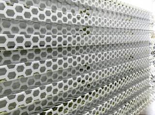
Does anyone have a suggestion how to render a perforated and corrugated metal cladding. The original material is shown in the photo below. Each fold is about 2 1/2".
I use VectorWorks but I am looking for a general approach so I would appreciate answers from users of other programs.
mleitner
Mar 26, 08 7:40 pm
Just to elaborate the question a bit:
1. Would you use a texture map build an actual object?
2. How do you convey the transparency created by the perforation?
3. How would could you imitate the depth of the folds?
xtbl
Mar 26, 08 7:57 pm
i have limited 3d modeling experience, but from what i remember from my formz class 4 years ago, you'd use a transparency map to create the holes, and perhaps a bump map for the corrugations.
i'm sure others will have more detailed help.
Carl Douglas (agfa8x)
Mar 26, 08 7:59 pm
Depends on how far the material will be seen from. If it's up close, then you need to model the square corrugations, and use a texture for the hex mesh. If it's only seen from a distance, then you are probably looking at three maps:
1. a metal material colour map
2. a hex mesh transparency map
3. a corrugated bump map.
mleitner
Mar 27, 08 11:55 pm
Thanks for the help. I'm working on making it happen (bump map is giving me a tough time), only a matter of time.
garpike
Mar 28, 08 12:09 am
1. I typically model the corrugations and use a transparency map for the perf.
2. Use a texture map (or in this case, call it a transparency map)
3. Model it the folds. It's precise.
will galloway
Mar 28, 08 5:29 am
i haver tried both methods above. garpikes gives best result, including from a distance.
trace™
Mar 28, 08 8:36 am
Model the profile, texture map the pattern. This is the only way you'll get accurate highlights.
mleitner
Apr 2, 08 12:59 pm
As suggested I modeled the corrugation and then applied a transparency map. The bump map just didn't result in the depth needed.
Now I just have to get the reflectivity and color tone right.
Thanks!
strlt_typ
Apr 2, 08 1:54 pm
model one hexagon
array
copy/paste/rotate
med.
Apr 2, 08 3:31 pm
I would just be afraid that if you modeled the corrugation it would eat up tons of ram and tank your system.
Like everyone said above, I would just create a transparency map with a bump map of the corrugated pattern.
rehiggins
Apr 2, 08 5:47 pm
bump mapping is for subtle surface variation and does not actually manipulate the model geometry (it's typically only a tweak of light/shadow effects)--To get the look of corrugated metal (at the range of the image above) you would need to use a displacement map which is an actual transformation of the model geometry done at render time. Sometimes displacement maps end up being just as 'heavy' as actual geometry though…
Appleseed
Apr 2, 08 6:28 pm
Model the the fold, use a transparency map for perfs.
Mamon Shareef
Sep 22, 14 3:12 pm
in revit
model the actual material with the folds and thickness
then find an image of a hexagon martial, use Photoshop to create positive and negative of the hexagon cutouts. create a new material and use the image for bump and cutouts
and in render display it should look like this (this is using a fence )
Miles Jaffe
Sep 22, 14 5:12 pm
The original post was from 6-1/2 years ago. Maybe the OP figured it out in that time. Or not.
Funny to note (also) that the OP posted 22 new topics and zero comments.
Mamon Shareef
Sep 22, 14 8:51 pm
Oops sorry for bringing up this old topic didn't pay attention to the date I was searching for corrugated metal and found this topic and since I did something similar I thought to give my two cents
Does anyone have a suggestion how to render a perforated and corrugated metal cladding. The original material is shown in the photo below. Each fold is about 2 1/2".
I use VectorWorks but I am looking for a general approach so I would appreciate answers from users of other programs.
Just to elaborate the question a bit:
1. Would you use a texture map build an actual object?
2. How do you convey the transparency created by the perforation?
3. How would could you imitate the depth of the folds?
i have limited 3d modeling experience, but from what i remember from my formz class 4 years ago, you'd use a transparency map to create the holes, and perhaps a bump map for the corrugations.
i'm sure others will have more detailed help.
Depends on how far the material will be seen from. If it's up close, then you need to model the square corrugations, and use a texture for the hex mesh. If it's only seen from a distance, then you are probably looking at three maps:
1. a metal material colour map
2. a hex mesh transparency map
3. a corrugated bump map.
Thanks for the help. I'm working on making it happen (bump map is giving me a tough time), only a matter of time.
1. I typically model the corrugations and use a transparency map for the perf.
2. Use a texture map (or in this case, call it a transparency map)
3. Model it the folds. It's precise.
i haver tried both methods above. garpikes gives best result, including from a distance.
Model the profile, texture map the pattern. This is the only way you'll get accurate highlights.
As suggested I modeled the corrugation and then applied a transparency map. The bump map just didn't result in the depth needed.
Now I just have to get the reflectivity and color tone right.
Thanks!
model one hexagon
array
copy/paste/rotate
I would just be afraid that if you modeled the corrugation it would eat up tons of ram and tank your system.
Like everyone said above, I would just create a transparency map with a bump map of the corrugated pattern.
bump mapping is for subtle surface variation and does not actually manipulate the model geometry (it's typically only a tweak of light/shadow effects)--To get the look of corrugated metal (at the range of the image above) you would need to use a displacement map which is an actual transformation of the model geometry done at render time. Sometimes displacement maps end up being just as 'heavy' as actual geometry though…
Model the the fold, use a transparency map for perfs.
in revit
model the actual material with the folds and thickness
then find an image of a hexagon martial, use Photoshop to create positive and negative of the hexagon cutouts. create a new material and use the image for bump and cutouts
and in render display it should look like this (this is using a fence )
The original post was from 6-1/2 years ago. Maybe the OP figured it out in that time. Or not.
Funny to note (also) that the OP posted 22 new topics and zero comments.
Oops sorry for bringing up this old topic didn't pay attention to the date I was searching for corrugated metal and found this topic and since I did something similar I thought to give my two cents